
Existing PV farm
Existing land, interconnection, and 100 MWdc+ PV. Dual-purpose the array as a 24/7 cooling asset. Modular compute plus the same thermal plant. Optional CSP, TES, and ORC. Then qualified heat recovery. No field expansion.
Platform
A cooling overlay on the PV farm you already have. Phase 0 is 50 MW. Phase 1 is 58.5 MW, cooling only. Phase 2 stays on the grid at 153.72 MW. Phase 3 is full off-grid at 175.04 MW. Same fence. Not a new interconnect.
Existing land, interconnection, and 100 MWdc+ PV. Dual-purpose the array as a 24/7 cooling asset. Modular compute plus the same thermal plant. Optional CSP, TES, and ORC. Then qualified heat recovery. No field expansion.
Existing compute and power envelope. Needs adjacent land — ideally with PV already installed. Ambient-air, buried-loop, and cold-storage cooling first. Additional compute on the existing generation interconnect next. Optional AI heat recovery after uptime isolation. Qualified generator recovery last.
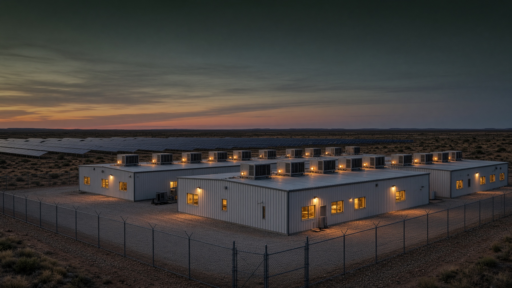
Cooling first
Phase 1 is open cassette rows and an air-cooled chiller. No dry coolers. No cooling towers.
Phase 2 and Phase 3 share one reject field. Jacket water sets the acres. About 76 acres, then 94.
Cooling first. About 50 MW of firm IT. No engines.
Then engines, still on the grid. 153.72 MW.
Then full off-grid. 175.04 MW. Same fence.
Phase 0
Months, not years
Workloads start while cooling is built.
Phase 1
6–12 months
About 50 MW of firm IT. No engines.
Phase 2
After the hall is up
153.72 MW firm IT. About 1.87 years.
Phase 3
After the engines are in
175.04 MW firm IT. Full off-grid. 2.22 years.
100 MWdc farm · Phase 0 is 50 MW · Phase 1 is 58.5 MW · then 153.72 and 175.04 MW · same fence. Pecos, Texas. The plant starts at 50 MW. Phase 1 is 58.5 MW, about $175.5 million a year, with no engines. Phase 2 is 153.72 MW on the grid, about $369.6 million a year, and pays for itself in 1.87 years. Phase 3 is 175.04 MW off the grid, about $405.2 million a year, in 2.22 years. The engine phases need a gas supply sized for them. Illustrative. Not a permit.
Two days at Pecos
These bars are that hall on a hot June day and a cold December day. Phase 1 is 58.5 MW and has no engines. Phase 2 is 153.72 MW and stays on the grid. Phase 3 is 175.04 MW and leaves the grid. The hour-by-hour set is on the cooling page.
17 June · hour-average temperature 44.4 °C at 15:00. Local standard time.
Same ~500-acre fence. Phase 0 is 50 MW. Phase 1 is 58.5 MW. Phase 2 stays on the grid at 153.72 MW. Phase 3 is full off-grid at 175.04 MW. Shared reject is about 35 acres, then 76, then 94.
See the conversion case on Economics.Revive PV
Repowering an existing PV farm should not start with a dumpster. Recover what can run. Recycle what cannot.
01
On-site take-down and triage. What can run stays in the loop.
02
Inspect, recoat, repair, and test in a two-container mobile factory.
03
Put recovered modules back to work. Recycle the rest.