
01
Convert capacity into compute
AI growth is limited by power delivered to servers and heat removed — not by nameplate generation alone.
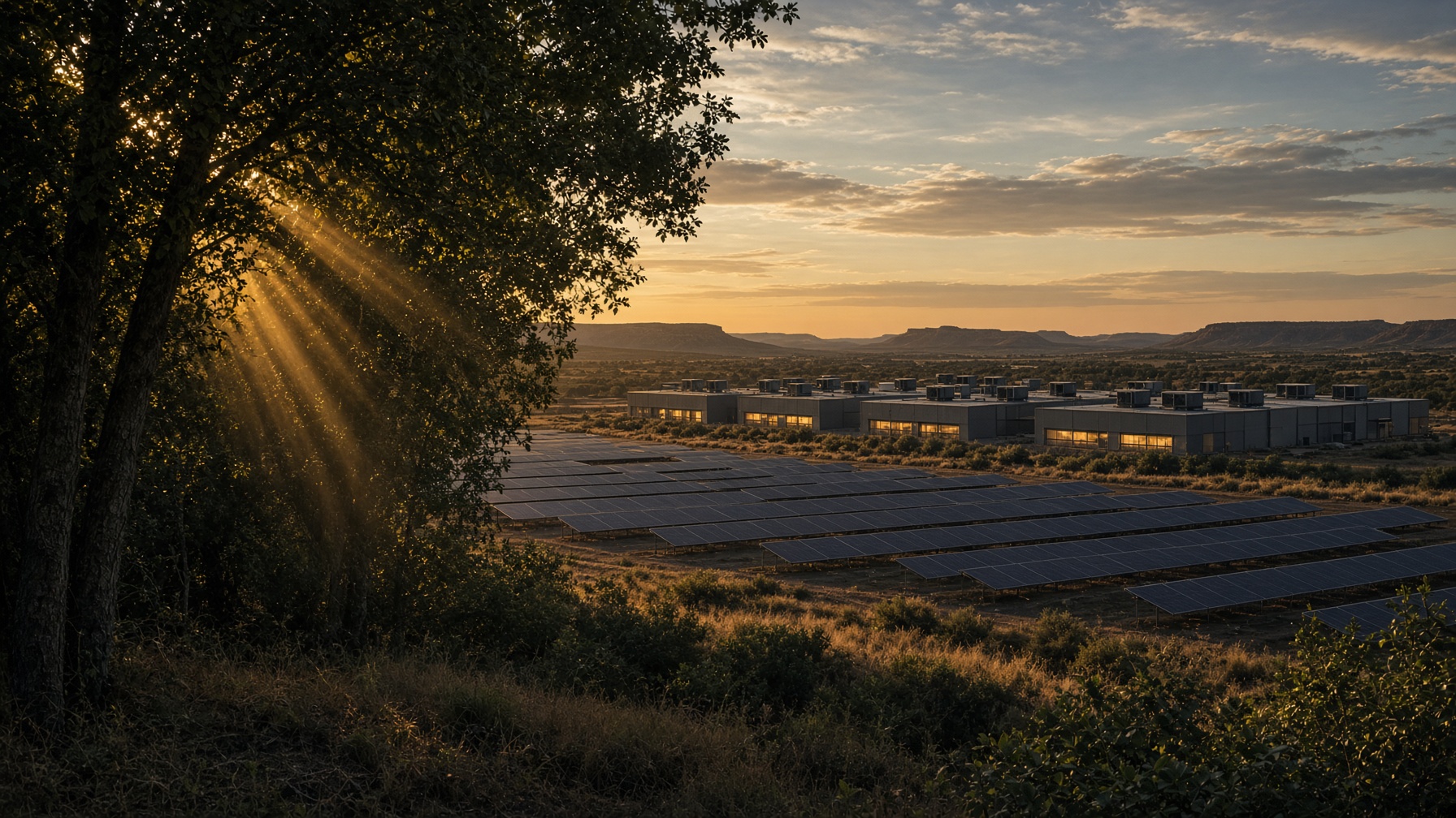
More Compute. Naturally.
Komorebi · (ko-moh-ray-bee)
Most of the field keeps making power. A slice of it takes the heat. Those freed megawatts go to GPUs, not chillers.
A cooling overlay on a plant that already exports — not a new power plant, and not a new interconnect. Cooling tables on a slice of the field. The rest stays PV. Dry coolers remain as backup.
The worked case is 50 MW of firm IT on an existing 100 MWdc PV farm. Cooling uses 8.5 MW less than chillers, so the meter reads 54 MW, not 62.5.
A cooling overlay on the fenceline you already have. Closing 50 MW of firm IT is $36–39 million — $0.72–0.78M per MW — against $150 million per year of planning offtake. Two comparisons: an already-connected solar deed becomes a 50 MW IT host this year; 8.5 MW less parasitic load versus PUE 1.25 at the same 50 MW. Original dry coolers stay as fail-safe.
Phase 1
Existing large PV farms in leading economies
~91 GW
AI compute these farms’ dual-use can host
Hybrid radiator tables and a heat-pump cold bank. 50 MW of design-target 99.9% firm AI per 100 MWdc.
Phase 2 / 3
Same land
~116 GW
Optional on the same land
TES/ORC and recovered-row CSP after Phase 1. Engines last. Not in the Phase 1 offtake. Peak / flexible ~149 GW. Qualifying plants, not signed contracts.
Pecos planning case
100 MWdc legacy farm / 50 MW firm IT / 8.5 MW parasitic cut / 500-acre 2015 fence. Phase 1 books 50 MW at the interconnect you already have. TES/ORC and extra halls are later, on the same fence.
50 MW firm IT. 8.5 MW parasitic cut (12.5 → 4 MW). Meter 54, not 62.5.
Pecos, Texas planning weather
Monthly mean MW. Lower is better. Cooling parasitics at each architecture on the same 50 MW hall. Shape from 2024 NSRDB for Pecos; means scaled to 12.5 MW at PUE 1.25 and 4 MW at Komorebi Phase 1.
Not gigawatts. The source files labeled monthly-mean MW as GWe. Scaled so the chiller line is the 12.5 MW PUE 1.25 block on a 50 MW hall. Komorebi is Phase 1 only — 50 acres of radiator tables — not later recovery.
100%
More AI compute per 100 MWdc — inclusive of the 8.5 MW parasitic cut. Weather and soils set the acres.
Existing
At the same interconnect
50 MW
Pecos planning case baseline
474 sites
U.S. existing-PV screen
Named case: 50 MW firm IT on 100 MWdc, inclusive of 8.5 MW parasitic recovery. Weather and soils set the acres. Pecos planning case — 100 MWdc legacy farm / 50 MW firm IT / 8.5 MW parasitic cut / 500-acre 2015 fence.
Three insights
The bottleneck in hyperscale AI is no longer compute demand. It is time-to-energy.
01
AI growth is limited by power delivered to servers and heat removed — not by nameplate generation alone.
02
Cooling, recovered heat, CSP, thermal storage, and ORC reinforce one another as one system.
03
Add each capability only when its incremental compute value exceeds its incremental cost.
Growth is constrained by the infrastructure required to support it — not by demand for servers.
Limited interconnect capacity and substation availability delay or cap growth.
Additional natural-gas supply, infrastructure, and permitting are slow and uncertain.
Cooling towers withdraw and evaporate water, creating permitting and environmental limits.
New infrastructure takes years and billions — stranding racks and delaying revenue.
Why capacity is left on the table
Nearly all IT electrical energy ultimately becomes heat.
Fuel and generation
Scarce interconnect and turbines are spent on cooling and support loads as well as GPUs.
Rejected heat
In high-temperature liquid-cooled configurations, a large fraction of that heat can be captured in the liquid loop. Komorebi models a 70°C source-loop condition — a design case, not an industry universal.
Groundwater loss
Towers withdraw and evaporate water, creating permitting and environmental limits year after year.
Phase 1 removes heat. Recovery comes later — after uptime is proven.
Remove heat first
Radiator tables on extra A-frames under cooler rows only. Remaining PV stays generation. Phase 1 is simpler and faster to implement.
Recover heat later
After uptime isolation, capture AI-server heat, then heat from qualified generation — each asset only when it pays.
Enable compute
Return electrical headroom to IT load — without requiring an equivalent new grid interconnection or material groundwater withdrawal. Later thermal recovery can use heat from qualified existing generation.
The product
Dual-purpose an existing PV farm as 24/7 cooling, then drop in modular AI. The hyperscaler is buying additional compute on an existing generation interconnect — not an equivalent new transmission line. Heat recovery is later. Phase 1 is the hall.
Existing land, interconnection, and 100 MWdc+ PV. Dual-purpose the array as a 24/7 cooling asset. Modular compute plus the same thermal plant. Optional CSP, TES, and ORC. Then qualified heat recovery. No field expansion.
Existing compute and power envelope. Needs adjacent land — ideally with PV already installed. Ambient-air, buried-loop, and cold-storage cooling first. Additional compute on the existing generation interconnect next. Optional AI heat recovery after uptime isolation. Qualified generator recovery last.
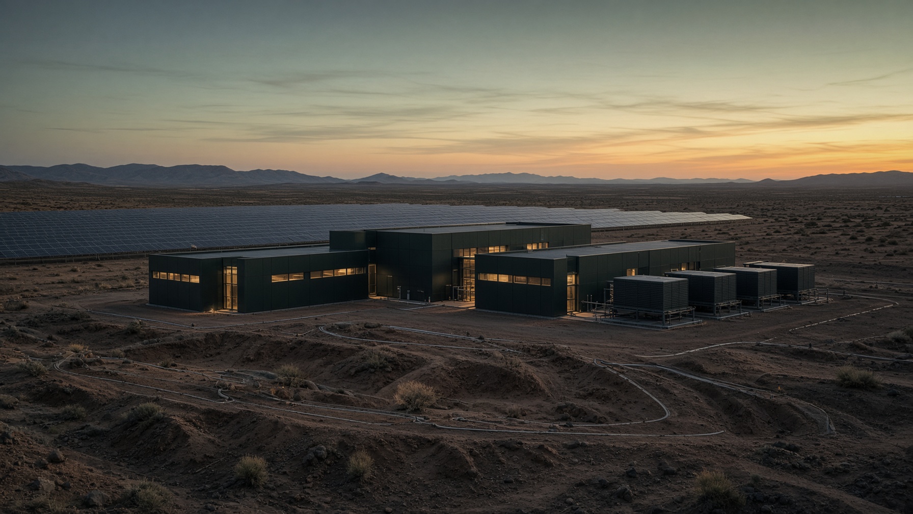
Architecture
Each layer is independently valuable. Phase 1 is the product — cooling, simpler and faster. Phase 2 is the filing and the plumbing. Phase 3 is the residual plant. No later stage may degrade rack cooling. Thermal recovery may be unavailable. Rack cooling may not.
01
Radiator tables and a cold bank cut parasitics. Phase 1 — simpler and faster.
02
After uptime isolation, capture AI-server heat, then heat from qualified generation when each asset pays.
03
Lift temperature with heat pumps and CSP only when incremental compute value exceeds cost.
04
Free electrical headroom for additional AI compute inside the same envelope.
Reliability principle
Thermal recovery may be unavailable. Rack cooling may not.
Opportunity set
Sequence
Start the hall. Put cooling on a slice of the tables you already have. Recover heat only after that hall is up. Foundations, optics, and offtake sit in the briefing — under NDA.
Phase 0
Months, not years
Workloads start while cooling is built.
Phase 1
6–12 months
More IT at the interconnect you already have.
Phase 2
After the hall is up
More compute from heat the site already makes.
Phase 3
After heat is booked
Same plant. More IT.
Platform
Radiator tables, a cold bank, and low-water heat rejection cut parasitic load and raise compute density per available megawatt.
On existing PV farms: repower legacy polycrystalline, monofacial arrays with higher-density bifacial modules on reflective foundations, recover aperture for Komorebi CSP, and add duration without expanding the site.
Optional NPI 4-lens, thermal energy storage, and ORC convert leftover acres into 14 MWe — on the same radiator loop. Dry cooler is fail-safe only, not the Phase 2 sink.
On existing PV farms: on-site triage, refurbishment, and redeployment with Revive PV turns aging modules from a repowering liability into a recoverable asset.
Start with an existing PV farm of the right age. Request a solution briefing. GPS, weather, generation, and soils are shared after NDA.